Rotating magnetic fields
The three-phase rotating magnetic field: poles, speed, air-gap field, counter-rotating fields
Foreword. This is a shortened version of the topics covered in full in the e-book Physics and Mathematics of the Rotating Magnetic Field. Here you will find the essential concepts and the boards to experiment with them; complete proofs and the mathematical developments are in the book, which you can reach through the link at the end of the lesson.
It is a magnetic field of constant strength that rotates at constant speed. It is produced by feeding three windings, 120°/p apart in space, with three currents 120° apart in time: the sum of the three alternating fields produced by the phases is a rotating vector. The parameter p is the number of pole pairs: in a 2-pole machine (p = 1) the windings are 120° apart, in a 4-pole machine (p = 2) 60°. It is the working principle of induction motors and synchronous machines.
Try it on the board ▸n1 = 60 f / p revolutions per minute, where f is the current frequency and p the number of pole pairs. At 50 Hz a 2-pole field (p = 1) turns at 3000 rpm, a 4-pole field (p = 2) at 1500 rpm; at 60 Hz, 3600 and 1800 rpm.
Try it on the board ▸They are the north-south pairs into which the windings divide the stator. With 4 poles per phase, wound in the sequence N-S-N-S, the field has 2 pole pairs (p = 2) and rotates at half the speed of the 2-pole field: speed is inversely proportional to p.
Try it on the board ▸Simply swap any two of the supply phases: for example, send current I3 into phase 2 and I2 into phase 3. The phase sequence reverses, and the field, and with it the motor, turns the other way.
Try it on the board ▸At the instant when phase 1 is at its peak, B1 = BM while B2 and B3 equal BM/2 and form 60° with B1: their components along B1 add 2 · (BM/2) · cos 60° = BM/2. The total is 1.5 BM, and it stays so at every instant if the currents are balanced.
Try it on the board ▸Galileo Ferraris, who demonstrated it in 1885 with two perpendicular coils carrying phase-shifted currents and published it in 1888. In the same years Nikola Tesla reached similar results and on May 1, 1888 was granted the patent for the polyphase induction motor.
Assuming iron with infinite permeability, only the air-gap crossings contribute to Ampère's circulation when the closed circulation line goes around a current. Taking a single coil for simplicity, the circulation is zero in the region inside the coil if the closed path encloses no current: this means that inside the coil the field is constant. A circulation line enclosing the whole coil also gives zero circulation, because the path encloses two equal and opposite currents, and this lets us say that in the region outside the coil, too, the field is constant, generally with a different value. Each coil therefore produces a rectangular field, and the sum of these fields gives a stepped shape.
Try it on the board ▸When a phase is distributed over q slots, the fields of the individual coils are shifted by the angle from one slot to the next. The winding factor ka (never greater than 1) is the ratio of their vector sum to the sum of their magnitudes: it tells how much the first harmonic of the field is reduced compared with a concentrated winding.
Try it on the board ▸An alternating magnetic field, fixed in direction and sinusoidal in time with amplitude BM, is at every instant the sum of two fields of constant amplitude BM/2 rotating in opposite directions at the same angular velocity.
Try it on the board ▸Splitting the three alternating phase fields with Leblanc's theorem, the three fields rotating one way are in phase and add up (1.5 BM); the three rotating the other way form a symmetric star and their sum is zero.
Try it on the board ▸1 - The discovery of the rotating magnetic field
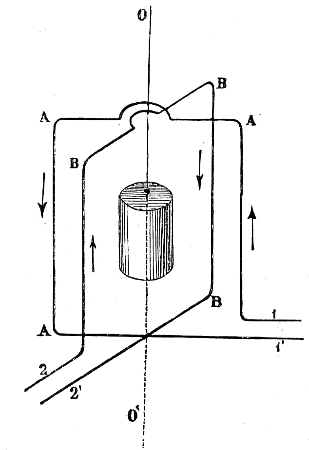
Figure 1 - Galileo Ferraris's experiment verifying the existence of the rotating magnetic field between two perpendicular coils. Diagram published in "Il Nuovo Cimento", Pisa, 1888
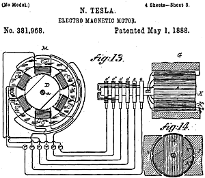
In the same years Nikola Tesla (1856-1943), a Serbian-American physicist and engineer, was obtaining similar results. Galileo Ferraris's studies, which also described a small induction motor, were published in April 1888 in the journal "Il Nuovo Cimento" (download the paper).
On May 1 of the same year Tesla was granted the patent for the induction motor.
With the introduction of three-phase power distribution, and thanks precisely to the discovery of the rotating magnetic field, the asynchronous (induction) motor quickly became widespread. It is still the most widely used rotating electrical machine in the world.
The rotating magnetic field is also the basis of the synchronous machine, which today is used mainly as a generator (alternator).
2 - The three-phase rotating magnetic field
 The board on the left shows the stator (1) of a hypothetical three-phase AC rotating machine. The gray part is the stator magnetic circuit which, together with the rotor magnetic circuit, amplifies and channels the magnetic fluxes the machine needs in order to work.

2.1 - Current direction convention
In the diagram, P1 marks the start of phase 1 and F1 its end. Let's follow the red conductor: we enter at P1, wind N turns (3 in the example) around the pole, leave following the red conductor to the pole opposite the first one, wind another N turns around it in the same direction and then leave from F1. Each phase therefore uses two diametrically opposite poles. We follow the same procedure for the other two phases, in green and light blue. Suppose for now that we feed only phase 1 with the current I1 and consider an instant when it reaches its positive peak value. We call the current "positive" if it is represented by a vector lying in the first or second quadrant, which therefore has a positive imaginary part(2).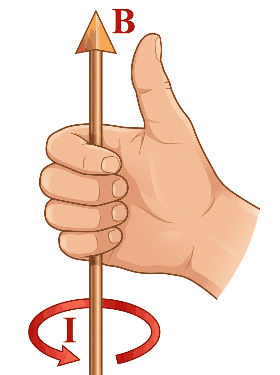
The arrows show the direction of the current in the windings, consistent with the so-called Maxwell's rule (or right-hand screw rule) shown in Figure 4.
By convention we call a current positive when it enters at the start of a winding and leaves at its end. The current I1, at the instant shown, is therefore positive. When I1 reaches its peak value in the opposite direction it will be considered negative: we will then see it enter at the end of the winding and leave at its start. The magnetic polarities obviously reverse over time, at the same frequency as the currents that produce the field. Note that as long as the vector I1 stays in the 1st and 2nd quadrants, the current direction and the magnetic polarities of the phase do not change; what changes is the strength of the magnetic field B1 produced by the current I1 and represented by a vector along the polar axis of phase 1.
The same holds for the other two phases, carrying the currents I2 and I3.
The distance between one magnetic pole and the next pole of the same phase, measured along the inner circumference of the stator, is called the pole pitch τ (tau). If r is the inner radius of the stator, in the case shown τ = r π. It is sometimes given as the central angle between two consecutive poles (here π radians), which amounts to setting r = 1.
2.2 - The rotating field
In any case, it is important to note that the currents produce three alternating magnetic fields, whose strength varies sinusoidally over time, following the currents that produce them.The instant-by-instant sum (3) of the three vectors gives a resultant vector that rotates at constant angular velocity while also keeping a constant amplitude.
It is easy to see that the resultant field, at the instant when one of the phases carries its peak current, points along the polar axis of that phase. This is why the flux produced by the resultant field can in turn be represented by a rotating vector in phasor diagrams referred to a single phase of the electrical machine.
It is just as easy to find the amplitude of the resultant field. If we again take the situation in which I1 has its positive peak value, B1 takes its maximum value, say BM, while B2 and B3 are equal to BM/2, since they are produced by currents whose instantaneous value is half the peak value. Note also that B2 and B3 form angles of 60° with B1. Given the symmetry of the two fields with respect to B1, the resultant field clearly points along B1 itself. All we need to do, then, is add to B1 the components of B2 and B3 along B1:
The rotational speed of the field depends on the frequency f of the three-phase current system.
Calling n1 the rotational frequency of the field, in revolutions per minute, from n1/60 = f we get the relation: n1 = 60 f, loosely called the "speed" of the field.
If the phase currents are equal, that is, if the system is balanced, the field has a constant magnitude over time. In this case we speak of a circular field. An imbalance in the currents makes the magnitude of B vary continuously: the motion of the field then looks irregular and is called an elliptical field, because the tip of the resultant vector B traces an ellipse.
2.3 - Reversing the direction of rotation
If we swap two phases, which means, for example, sending current I3 into phase 2 and current I2 into phase 3, the direction of rotation of the field reverses. The example simulates exactly this swap of I2 and I3. Any pair of phases can be swapped to reverse the field.3 - Pole pairs and speed of the rotating magnetic field
We have already seen that the speed of the rotating field is set by the frequency of the stator currents and is directly proportional to it: doubling the frequency, for example, doubles the rotational speed. But another factor affects the speed: the number of pole pairs of the rotating magnetic field.3.1 - Pole pairs of the magnetic field
To understand the idea of the field's polarity, consider the following.The resultant field produced by a system like the one on the board on the left can be thought of as produced by two rotating magnetic poles that form in the stator. The field lines leave the north pole and enter the south pole. A magnetic field like this is called two-pole. We can confirm this by looking at the instantaneous magnetic polarities of the poles: the stator always appears divided into two zones, each containing only south poles or only north poles.
The rotational frequency of a two-pole field equals the frequency of the currents that produce it: if the current frequency is 50 Hz, the "speed" of the field is 50 revolutions per second, or 3000 revolutions per minute, as the formulas above also give.
Now suppose that the system is built as shown on the left. Each phase has four poles. They must be wound so that the currents create magnetic poles alternating in the sequence north-south-north-south. For phase 1, from the top pole near the start P1, we move to the pole 90° clockwise, then to those at 180° and 270°. By paying attention to the direction in which the turns are wound around the poles, the current I1 of phase 1 creates four alternating magnetic poles N-S-N-S arranged as in the picture. The same goes for phase 2 and phase 3. The overall effect of the three currents is then to divide the stator, magnetically, into four zones, each acting in turn as a north pole and a south pole. There are therefore two north-south pole pairs, and the field is called 4-pole or four-pole. Here too we can think of the rotating field as a set of 4 rotating magnetic poles that form in the stator. The lines of the resultant field leave the stator's north poles and enter its south poles.
Remarkably, this field rotates at half the speed of the previous case. If the current frequency is 50 Hz, the field makes 25 revolutions per second, 1500 revolutions per minute.
3.2 - Speed of the field
What we have just seen holds in general: the speed of the rotating field is inversely proportional to the number of pole pairs. So we define the quantity p = number of pole pairs. We will then speak of a field, a winding or a machine with p pole pairs. A two-pole machine has p = 1, a four-pole machine p = 2, and so on. Clearly 2p is the number of poles: if p = 2 the field has 2p = 4 poles, if p = 3 it has 2p = 6 poles, and so on.We can then write a more general law for the speed of the rotating field:
For a four-pole machine, the pole pitch τ is given by \( \tau= \frac{r \pi}{2}=\frac{r \pi}{p} \).
4 - Air-gap magnetic field in isotropic machines
A construction often used for electrical machines based on the three-phase rotating field (induction motors, synchronous motors and generators) is the so-called "non-salient-pole" (cylindrical-rotor) configuration. A non-salient-pole machine, also called isotropic, has a uniform air gap(4).By contrast, salient-pole or anisotropic machines have a non-uniform air gap, which makes the reluctances of the magnetic circuit non-uniform as well.
In an isotropic machine the conductors that make up the windings are placed in channels, or slots, cut into the stator and rotor magnetic circuits. The slots are evenly distributed along the cylindrical surfaces of the stator and rotor (Figure 5, which however does not show the rotor slots).
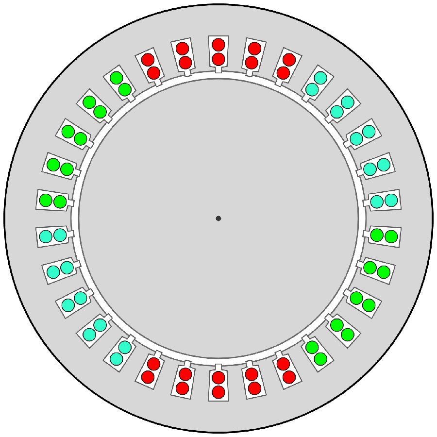
Figure 5 - Cross-section of the stator of a two-pole isotropic electrical machine, with the slots holding the phase conductors.
 we can get close to the ideal condition.
Figure 5 shows the stator of a two-pole isotropic machine.
The winding of each phase occupies 10 slots, so we have q = 5 slots per pole per phase. We have introduced here the parameter q, the number of slots per pole per phase. The colors show which phase each conductor belongs to.
4.1 - Air-gap field of an isotropic machine
To find the magnetic field in the air gap of an isotropic machine we will use Ampère's circuital law and a few simplifying assumptions that make the calculation easier without taking away the validity and generality of the results.4.2 - Simplifying assumptions
To study the magnetic field in the air gap it helps to rely on a few assumptions that simplify the analysis:- The magnetic reluctance of the paths in the material the stator and rotor are made of is zero: ℜm = 0 or, equivalently, their magnetic permeability is infinite, μ = ∞
- The field has the same configuration in every plane perpendicular to the machine axis
- The field lines leave and enter the infinitely permeable material perpendicularly and can be considered radial in the air gap
4.3 - The air-gap field: circulation and solenoidality
In the lower right part of the board we see a portion of stator and rotor, unrolled into a straight line. The current in conductor 1 flows out of the page (toward the observer), the current in conductor 2 flows into it. We call δ (delta) the thickness of the air gap.To compute the circulation we choose a closed path in the magnetic field, for example an oriented closed line around conductor 1.
The circulation can be computed by dividing the path into small segments \(\Delta l \), computing the scalar product \(H \cdot \Delta l\) for each of them and adding up until the whole closed line is covered. In our case, since we set \(H= 0\) in the stator and rotor, the only contributions to the circulation come from the segments crossing the air gap, of length \(\delta \). This length is usually small enough for the field to be considered constant along the whole segment \(\delta \). The field at points A and B due to conductor 1 has, given the current direction, the pattern shown: \(H_A \) pointing down, \(H_B \) pointing up. For a correct calculation of the circulation, however, it is convenient to fix a positive direction for the field(5) in the air gap. Let us take as positive, for example, a field directed from the stator to the rotor. A contribution to the circulation is then positive if the line's orientation agrees with the positive direction of H, negative otherwise (6). The orientation of the line is arbitrary too; here we chose counterclockwise (the same as the field lines of conductor 1).
Then, with these assumptions:
Now consider a second circulation path lying between the two conductors. The circulation is:
This last relation tells us that \(H_D = H_E \); since the only constraint we set is that the line lies between conductors 1 and 2, we can say that \(H_D = H_E = H_B\) and conclude that between conductors 1 and 2 the field must be constant and equal, for example, to \(H_B \).
Finally, consider a third closed line enclosing both conductors. Since, from our point of view, the two conductors are the active sides of one turn (or of one winding), the two currents are equal and opposite. Then:
We now already know a good deal about the field in the air gap: under our assumptions it has a rectangular shape, like the one shown in the upper part of the board.
The second condition comes from the solenoidality of the magnetic field: the flux entering the stator cylinder equals the flux leaving it. Together, the two conditions give the value of the field in the two segments, which depends on the angle α subtended by the coil at the center. When the conductors divide the stator into two equal parts (α = π) the two fields are equal except for their direction:
4.6 - Field of a distributed winding
Now let's look at a winding spread over several slots. In the example, imagine that the conductors of one phase are distributed over 3 slots, each at an angular distance θ from the next. Assuming α = π we get rectangular fields, as we have already seen. Here too we compute the field for each pair of corresponding conductors (each coil): pair 1-1' produces the highlighted rectangular field H1, similar to the field H2 of pair 2-2' and to H3 of pair 3-3', which however are shifted by a distance r⋅θ from one another (in the graph the radius is set to r = 1). Superposing the three fields gives a stepped resultant field. These rectangular fields can be obtained as a superposition of sinusoids, that is, they can be expanded in a Fourier series. The field H1, for example, can be approximated as:
which contains the first three terms of the Fourier series. The phase β accounts for the shift with respect to the origin of the axes.
As a first approximation, each rectangular field can be represented by the fundamental sinusoid, or first harmonic; for H1:
which greatly simplifies the calculations. The price to pay, however, is that we neglect the harmonic content of these waveforms, which matters most for synchronous generators, where the generated voltages must be sinusoidal to a high degree of accuracy.
In motors, harmonics in the rotating field mainly mean higher losses and parasitic torques, which in some situations can make operation irregular.
The resultant field is the superposition of the three rectangular waves H1, H2, H3, and it too can be expanded in a Fourier series. The first harmonic of H is then obtained as the superposition of the three fundamentals of H1, H2 and H3, or it can be found directly from the expression:
where q is the number of slots per pole per phase (3 in the example) and ka, known as the winding factor, is a correction coefficient (never greater than 1) that accounts for the phase difference between the sinusoids (and the phasors that represent them) caused by the angular shift θ from slot to slot. ka is essentially the ratio between the vector sum of the fields and the algebraic sum of their magnitudes \(k_a=\frac{\sum \vec H_i}{\sum H_i}\) and can be computed quickly with the formula shown on the board.
5 - Rotating magnetic field in an isotropic machine
Having seen how to find the magnetic field of a distributed winding, we still have to study the rotating field produced by a stator with a distributed three-phase winding. The board shows a cross-section of the stator of a 4-pole (p = 2) isotropic machine. The winding uses 3 slots per pole per phase. As usual, the phases are shown in different colors. With the same current-direction conventions adopted earlier, we can show the sequence of the instantaneous directions of the currents in the phase conductors. They produce 4 stator magnetic poles rotating at a speed:5.1 - How the rotating field behaves in the air gap
Let's now try to visualize the rotating field in the air gap. To do so, we have drawn the stator in a schematic, linearized form with its conductors, also marking the start of each phase (P1, P2, P3).To begin with, we feed the system only with the current I1. We immediately see the stepped field we already studied in 4.6. It is an alternating field, because the current producing it varies sinusoidally over time, but it is fixed in space. The same applies to the fields produced by the current I2 and by the current I3.
The magnetic field created by one phase therefore has a time period \(T = \frac 1 f\) and a spatial period \(T_S=\frac{2\;\pi\;r}{p}\), where r is the radius of the inner circumference of the stator, f is the frequency of the stator currents and p is the number of pole pairs.
In the example (r = 1, p = 2) we see two complete oscillations, so the spatial period is TS = π.
The instant-by-instant superposition of these three fields along the whole air gap produces a resultant field that travels (along the air-gap circumference) at constant speed toward the right. We see at once that the field does not keep its shape exactly as it moves. A basic periodic shape is clearly recognizable, but its details (the peak value, the relative position of the steps) change continuously. This observation matters for some of the remarks that follow.
This field too is a periodic function of time, with \(T = \frac 1 f\), and of space, with period \(T_S=\frac{2\;\pi}{p}\) (r = 1). The period is twice the pole pitch τ.
The number of spatial oscillations contained in the angular extent (2π) of the stator depends on the number of pole pairs. A 4-pole field must show two complete spatial oscillations N-S-N-S. This is why p, the number of pole pairs, is exactly the spatial "oscillation" frequency of the field.
Likewise, if the trigonometric function cos(x) shows a single oscillation in its spatial period 2π, in the same period the function cos(p x) shows p oscillations.
As a first approximation we can describe the field with a sinusoid, which we will call the fundamental sinusoid (or simply the "fundamental").
The fundamental sinusoid must match the stepped function as closely as possible. So, instant by instant, it must "follow" the magnetic field.
What, then, is the analytical expression of this "traveling" sinusoid?
 Activity 1: find the traveling sinusoid
The result of the activity above should be a sinusoid that travels with the stepped magnetic field, at the same speed, with as many spatial oscillations as the field. Things to consider:

- all four variables x, t, ω, p come into play
- it can help to look separately at the effect of the spatial and time variables: for example, how does a function that depends only on t behave? And one that depends only on x?
6 - Counter-rotating fields and Leblanc's theorem
Here on the left we see a vector B drawn at a given position in space (an x-y plane). Once its direction is fixed, this vector can be constant in direction and magnitude, in which case a (t, B) graph describing the vector as time goes by would simply be a straight line parallel to the time axis. Alternatively, the vector can vary over time according to some law f(t). Of particular interest for applications, and for this study, is the case where f(t) is sinusoidal. The magnitude and direction of the vector then change over time, giving what is called an alternating vector. As a function of time, a vector of this kind is expressed by \( B(t)=B_M cos(\omega t +\varphi) \).Leblanc's theorem(7) states that an alternating vector can be obtained, instant by instant, as the sum of two vectors of constant magnitude 1/2BM that rotate in opposite directions at the same angular velocity: B = BCW + BCCW, where BCW is the clockwise field and BCCW the counterclockwise field. At the initial instant they form the angles −φ and φ with B. The result holds for any direction of B, as you can see by varying the angle θ.
6.1 - The three-phase rotating field as a sum of counter-rotating vectors
Each of the alternating magnetic fields produced by the stator phases can be split into two counter-rotating fields, called Dk and Sk (k = 1, 2, 3) for simplicity. So, for example, D1 is the clockwise (CW) field produced by phase 1, while S1 is the corresponding counterclockwise (CCW) field.
Splitting the
field B1 gives the two vectors D1 (solid line) and S1 (dashed).
Look also at how the field B2 and the
field B3 split.
Now let's show only the
six counter-rotating fields.
Here we see that the D fields are in phase (they are drawn side by side rather than on top of one another, so that they are all visible), and their sum gives the resultant field B, which clearly has magnitude 1.5 BM (see 2.2) and rotates at the same angular velocity as the D fields. The sum of the S fields, which form a symmetric star of vectors, is zero, as is well known(8).
6.2 - Books by the author
All the author’s books: books page.
(1) The stator is the stationary part of an electrical machine; the rotor is the moving part. The stator image was made with an application by Prof. Mirsad Todorovac - Chair for Electronic and Informational Systems - University of Zagreb (Croatia).

(2) It is worth clarifying, or recalling, an important aspect of the vector representation of sinusoids.
In physics, oscillations are usually described with the cosine function. As a result, quantities with a "concrete physical meaning", that is, quantities that can somehow be measured, are represented by the real part of a complex number. In electrical engineering it has become common to express sinusoidal quantities with the sine function, so the "physical", "measurable" values of those quantities are represented by the imaginary part of a complex number, that is, by the projection of the rotating vector on the vertical axis (imaginary axis). From the point of view of the mathematical description, very little changes: it is just a phase difference of π/2, which simply shifts the starting instant. See also: Complex numbers and Sinusoidal alternating quantities on this site.
(3)Adding magnetic fields in magnetic circuits with ferromagnetic materials is a delicate operation, because magnetic saturation makes the system nonlinear . Superposition is strictly valid only if the system works in the linear region of the magnetization curve
(4) The air gap is the layer of air between stator and rotor that the rotor needs in order to turn. It should be small, to reduce magnetizing currents and leakage fluxes. In the induction machine the maximum torque depends strongly on the air-gap width, so to get a high maximum torque it is essential to make the gap as small as possible (from fractions of a millimeter to 2 mm, depending on the power).
(5) Why not compute the circulation using the actual directions of the field? It would certainly be possible, but in cases like this one it would make it hard to choose the circulation paths consistently. For example, we could not consider paths enclosing currents in opposite directions: we would get completely wrong field values.
(6) Recall that the contribution H⋅Δl to the circulation is a scalar product of vectors, so H⋅Δl = H⋅Δl cos α, where α is the angle between H and Δl. If α > 90°, cos α < 0 and the contribution is negative.
(7) Maurice Leblanc (Paris 1857 - Paris 1923), French engineer. He worked on the development and improvement of the induction motor and introduced the "Leblanc damper winding" to damp the hunting oscillations of alternators. He was one of the first to work on the transmission of moving images: television.
(8) See, for example: Three-phase systems: generating a symmetrical set of voltages, on this site.
© 2026 - Sandro Ronca - All rights reserved - Legal notes