Rifasamento degli impianti elettrici
Power factor correction in electrical installations
1 - Reactive power
 Almost
all industrial electrical loads behave like a
resistive-inductive impedance, so the current
lags the voltage by an angle \(\small \varphi_u\)
(1). This
phase shift means that there is an exchange of reactive
power between
generator and load. Electric motors, for example, work through
the interaction of a magnetic field with the currents flowing in
their circuits. Building up the magnetic field
requires the energy carried by reactive power, inductive in this case.
As is well known, reactive power cannot be used to do work outside
the electrical system, but it still has to be produced by the generators
and made available to the devices that need it.
It is continuously exchanged between generators and
loads and occupies the transmission lines with the corresponding current,
also called reactive
current.
 Activity
1
2 - Active current and reactive current
The current drawn by the load can be split into two components:the active current, in phase with the voltage, given by:
\[I_a = I_u\,cos\,\varphi_u \]
and the reactive current already mentioned, in quadrature with the voltage:
\[I_r = I_u\,sin\,\varphi_u \]
Of course, for a given supply voltage V, the active component is proportional to the active power:
\[P_u = V\,I_u\,cos\,\varphi_u = V\,I_a \]
while the reactive component is proportional to the reactive power:
\[Q_u = V\,I_u\,sin\,\varphi_u = V\,I_r \]
The supply network and the generators must deliver to the load both the active power, which will be used to do work, and the reactive power it needs.
However, we know that inductors and capacitors behave in complementary ways as far as reactive power is concerned: supplied by the same sinusoidal AC voltage, the capacitor delivers reactive power when the inductor absorbs it, and vice versa.
3 - Power factor correction
This suggests that the exchange of reactive energy, which normally takes place between load and generator, could instead take place between a resistive-inductive load and a capacitor connected in parallel with the load itself.The parallel connection is of course meant to leave the voltage across the load (simulated by the R-L impedance) unchanged, and therefore the way the load itself works.
If we connect the capacitor we immediately see that the phase angle is reduced and at the same time the magnitude of the current decreases.
Looking more closely, we also notice that the current drawn by the load \(I_u\) has not changed.
The current in the capacitive branch, leading the voltage by 90°, added to the current \(I_u\), gives the total line current \(I_T\).
The phase angle φu has not changed either, which confirms that the load works exactly as it did before the capacitor was connected, drawing the same current, the same active power and the same reactive power.
The reactive power carried by the line has decreased instead, because part of the energy exchange now takes place directly between inductor and capacitor. In fact the reactive component of the total current has decreased.
The active component of the current stays constant, which confirms that the active power drawn does not change. On the other hand the capacitor only absorbs reactive power and so cannot change the situation in that respect.
If we also draw the reactive component \(\small I_{ur}\) of the current drawn by the load, we can write a few important relations. For example:
\[I_a = I_T\,cos\,\varphi = I_u\,cos\,\varphi_u\]
which states that the active components of the total current \(I_T\) and of the load current \(I_u\) are equal.
The reactive component of the total current can be found from the active component:
\[I_r = I_T\,sin\,\varphi = I_a\,tan\,\varphi\]
and the same holds for the reactive component of the load current \(I_{ur}\):
\[I_{ur} = I_u\,sin\,\varphi = I_a\,tan\,\varphi_u\]
From the phasor diagram we see that the capacitor current can be seen as the difference between the two reactive components:
\[I_c = I_{ur} - I_r\]
Using the previous formulas:
\[I_c = I_a\,(tan\,\varphi_u - tan\,\varphi)\]
Multiplying both sides of this relation by V we get:
\[V\,I_c = V\,I_a\,(tan\,\varphi_u - tan\,\varphi)\]
and therefore:
\[V\,I_c = V\,I_u\,cos\,\varphi_u\,(tan\,\varphi_u - tan\,\varphi)\]
Since \(V\,I_c = Q_c \) is the reactive power absorbed by the capacitor, while \(V\,I_u\,cos\,\varphi_u \) is clearly the active power absorbed by the load:
\[Q_c = P_u\,(tan\,\varphi_u - tan\,\varphi)\]
This is also called the correcting reactive power.
Since:
\[Q_c = \frac{V^2}{X_c} = \frac{V^2}{\frac{1}{\omega C}} = \omega\,C\,V^2\]
we can find the correcting capacitance:
\[C = \frac{P_u}{\omega V^2}\,(tan\,\varphi_u - tan\,\varphi)\]
Activity 2: Problem
In theory the load could be fully corrected, bringing the total current in phase with the voltage. In that case, since \(\varphi = 0\) and \(tan\,\varphi = 0\), we would have:
\[C = \frac{P\,tan\,\varphi_u}{\omega\,V^2} = \frac{Q_u}{\omega\, V^2}\]
but this is not normally the goal, because an "overcorrection", which could occur when operating conditions change, must be strictly avoided, as it would make the load capacitive overall. Capacitive loads are undesirable because of the overvoltages they can cause at the receiving end of the supply line (Ferranti effect, fig. 1).
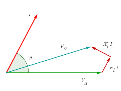
Fig. 1 - The Ferranti effect. With strongly capacitive loads the receiving-end voltage \(\small V_u\) of the line can exceed the sending-end voltage \(\small V_0\).
4 - Power triangle
The effect
of power factor correction is very clear if we look at
the power triangle. When we connect
the capacitor
the active power stays the same while the total reactive and
apparent power decrease, even though the reactive power absorbed
by the load does not change.As already said, capacitive reactive power must not be fed into the network, so as a precaution the power factor is corrected to a value below unity.
In Italy the electricity distributor uses 0.9 as the reference value.
Installations with a lower power factor are penalized with a higher energy price. If the power factor is 0.7 or lower, correction is mandatory.
5 - Ratings of the capacitor bank
A capacitor bank of capacitance C delivers its rated reactive power when it is supplied at its rated voltage:\[Q_{Cn} = \frac{V_n^2}{X_C} = \omega\,C\,V_n^2 \]
which clearly depends on the square of the voltage.
If the bank is used at a voltage different from its rated voltage, at the same frequency, the correcting power is:
\[ Q_C = \omega\, C\, V^2 = Q_{Cn}\,\frac{V^2}{V_n^2}\]
Then, since:
\[I_C = \frac{V}{X_C} = \omega\,C\,V\]
the rated current is:
\[I_{Cn} = \omega\,C\,V_n \]
and therefore:
\[I_C = I_{Cn}\, \frac{V}{V_n}\]
6 - Three-phase power factor correction
In a three-phase system, the correcting capacitance also depends on how the capacitors are connected.With capacitor banks connected in star (wye), if V is the line-to-line voltage and E the phase voltage, we have:
\[C_Y = \frac{P}{3\,\omega\, E^2}\,(tan\,\varphi_u - tan\,\varphi)\]
and since \(\small E = \dfrac{V}{\sqrt{3}}\), substituting into the previous formula:
\[C_Y = \frac{P}{3\,\omega\, \left(\frac{V}{\sqrt{3}} \right)^2}\,(tan\,\varphi_u - tan\,\varphi) = \frac{P}{\omega\, V^2}\,(tan\,\varphi_u - tan\,\varphi)\]
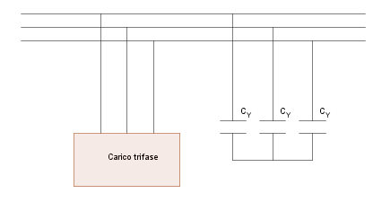
Fig. 2 -
Three-phase power factor correction with star-connected capacitors
In the delta connection, since V is also the phase voltage:
\[C_D = \frac{P}{3\,\omega\, V^2}\,(tan\,\varphi_u - tan\,\varphi)\]
The conclusion is that with this connection we get the same effect using capacitors with one third of the capacitance needed with the star connection:
\[C_D = \frac{C_Y}{3}\]
For this reason, at low voltage, capacitor banks are always connected in delta.
At medium-high voltages the star connection may be preferable for insulation reasons, since the capacitors can then be rated for a voltage \(\sqrt{3}\) times lower.
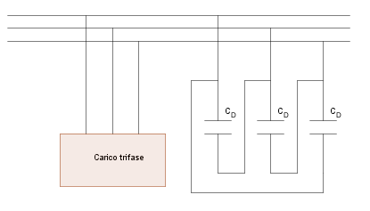
Fig. 3 -
Three-phase power factor correction with delta connection
7 - Benefits of power factor correction and regulations
To sum up, the benefits of correct power factor correction are:- lower line current under the same operating conditions of the loads; it is therefore possible to reduce the cross-section of the conductors or to supply more loads with the same line
- lower line losses, which are proportional to the square of the current
- lower voltage drops on the line
Rules in Italy for installations with a contracted power above 16.5 kW:
- the monthly average power factor cannot be below 0.7
- the minimum instantaneous power factor at maximum load during peak periods is 0.9
- with 0.7 < cos φ < 0.95 the energy in time bands F1 and F2 is subject to a surcharge
- feeding (capacitive) reactive power into the network is strictly forbidden (overcorrection)
8 - Related topics and further reading
- Electric power in sinusoidal AC circuits
- The author’s books
- AC 1: sinusoidal electrical quantities
- AC 2: impedance, reactance, series RLC, voltage resonance (in Italian)
- AC 3: admittance, parallel RLC, current resonance (in Italian)
- Complex numbers 1: definitions and basic operations (in Italian)
- Complex numbers 2: Euler's formula, complex powers and logarithms (in Italian)
(1) The subscript 'u' refers to the quantities of the load, here simulated by a resistive-inductive impedance. Any device that draws electric power is called a load (electrical load).
